Get in Touch With Us and Tell Us About Your Toughest Monitoring and Control Challenges.
SignalFire Telemetry products connect you with crucial product and hardware data at any of your oil and gas operation sites—whether it’s a pump, pipeline, or storage tank.

SignalFire Telemetry devices install anywhere water asset monitoring is needed, whether it’s for collection purposes, treatment, or delivery.

SignalFire Telemetry devices can monitor key assets and can do it affordably, without any renovation or high-priced engineering costs. They install easily with no required cable or additional power. The data is available on your phone or computer and the cloud service can even output to your corporate system to integrate with the rest of your data and keep your operation running.

SignalFire Telemetry devices can monitor and manage water supplies and additives throughout the property, helping you avoid catastrophic shortages and keep your irrigation plan on track.

Avoid costly product loss in bulk storage tanks, terminals, and transportation movements. Whether calling for tank levels, gauge pressure, or even movement pumps or pipelines, SignalFire products can fill any monitoring gap throughout a facility.

Environmental fines for businesses are frustrating and can bring business to a standstill until they’re worked out. No business wants to hurt the environment, and in competitive markets stopping production affects the bottom line and staff. But there are effective and affordable solutions with SignalFire Telemetry devices.

Expand visibility and control of your refinery or petrochemical processing facility without expensive renovations or redesigns. And do it with your current gauges and hardware. SignalFire telemetry devices are designed to work in harsh chemical environments and meet the strictest safety and security standards

No matter the size of your service map, monitoring remote assets ensures efficiency and keeps your operation in compliance. That’s how SignalFire devices can really help, offering the most affordable and effective monitoring solution that will monitor liquid, gas, electricity, and other assets.

Explore the diverse applications of SignalFire Wireless Telemetry Systems across different industries.

Access our latest brochures to explore comprehensive information about our products and services.

Easily find the sensors that are compatible with our systems on this dedicated page.

Explore a comprehensive collection of images showcasing our products, installations, and real-world applications.

In addition to monitoring various sensor data and transmitting that data to the Gateway, the SignalFire wireless system is capable of control applications that involve turning remote assets on/off. The decision to switch one or more remote devices on/off requires control logic. Instead of using a traditional SCADA or PLC, the logic is programmed and executed entirely within the SignalFire gateway saving the cost of hardware, software and programming.
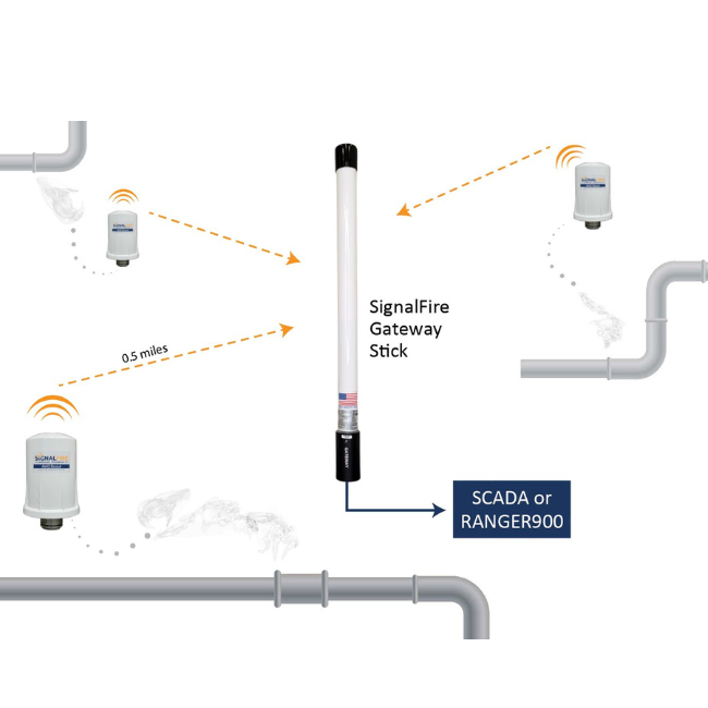
While SCADA systems and local PLC’s often require complicated configuration or ladder-logic programming, the SignalFire gateway embeds the control logic that consists of a simple IF/THEN table using any variables from any node available at the gateway. As an example application, let’s consider a system consisting of two tanks with the level being monitored using Sentinel wireless units. The tank levels are being fed by a pump controlled using the discrete output switch from a SignalFire RSD stick based on the level measured a Sentinel equipped with a level transmitter. See diagram below.

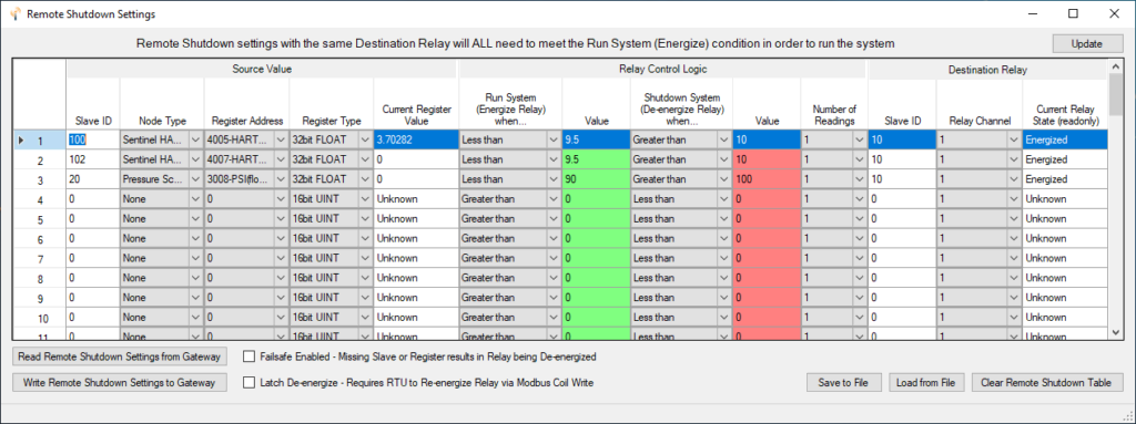
The desired logic is IF either tank exceeds a high level of 10 feet or if the discharge pressure exceeds 100psi THEN the pump should be shut off. This control logic can be easily configured in the gateway using the SignalFire ToolKit software.
First when connected to the gateway, select the “Remote Shutdown Settings” from the Settings menu, this will open the RSD control logic table. Each row in the table is considered one logic rule consisting of the source value settings, the relay control logic setting and the destination relay settings.
On our example we have two tanks and one pressure that we want to control the same pump. To accomplish this, we will assign three rules as discussed all with the same Destination Relay. For a given Destination Relay, ALL rules must satisfy the “Run state” for the relay to be energized. If any rule triggers the shutdown threshold the relay will be de-energized, and the pump will be shut off.
All SignalFire devices used for shutdown applications also include configurable internal failsafe timers. This allows the user to configure the devices to automatically shut down should the wireless communications be lost for any reason. The SignalFire Gateway also logs shutdown events in its internal non-volatile event log which can be read using the SignalFire ToolKit. Also, the recent shutdown history can be read via a set of Modbus registers to be monitored by a SCADA system of local HMI.
The internal control logic is simple yet powerful and allows operators to implement wireless control systems in a fraction of the time compared with hardwiring sensors and complex PLC programming. Additional details on the SignalFire shutdown logic configuration can be found in the Gateway user manual.
Get in Touch With Us and Tell Us About Your Toughest Monitoring and Control Challenges.


"*" indicates required fields
