Oil & Gas

SignalFire Telemetry products connect you with crucial product and hardware data at any of your oil and gas operation sites—whether it’s a pump, pipeline, or storage tank.
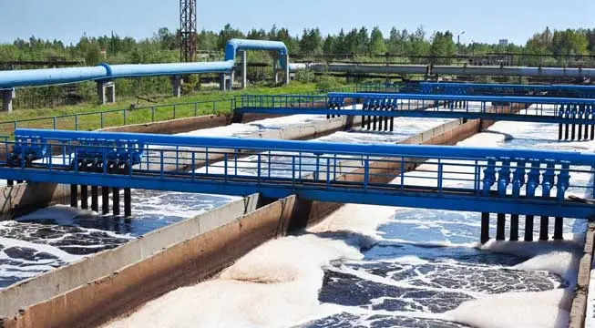
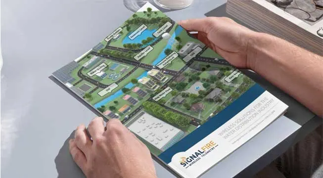
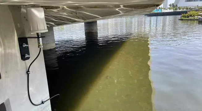
Water & Wastewater

SignalFire Telemetry devices install anywhere water asset monitoring is needed, whether it’s for collection purposes, treatment, or delivery.

General Industrial

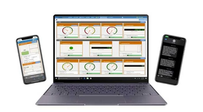
SignalFire Telemetry devices can monitor key assets and can do it affordably, without any renovation or high-priced engineering costs. They install easily with no required cable or additional power. The data is available on your phone or computer and the cloud service can even output to your corporate system to integrate with the rest of your data and keep your operation running.
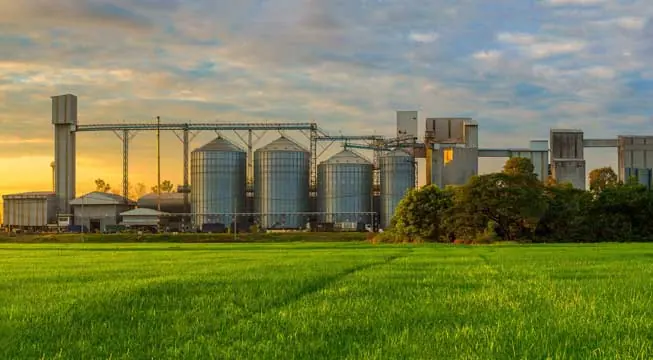
Agriculture

SignalFire Telemetry devices can monitor and manage water supplies and additives throughout the property, helping you avoid catastrophic shortages and keep your irrigation plan on track.
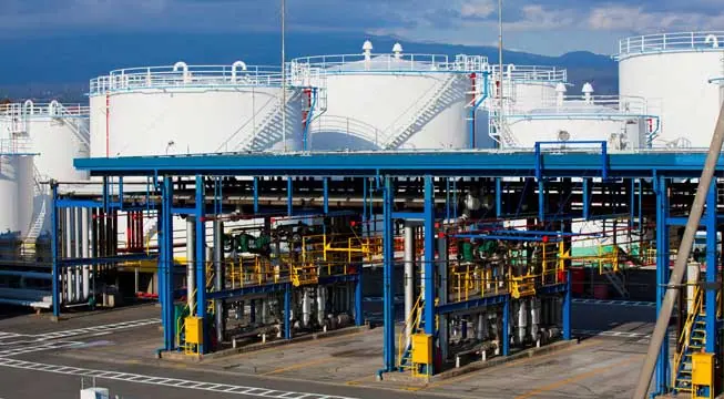
Tanks & Terminals

Avoid costly product loss in bulk storage tanks, terminals, and transportation movements. Whether calling for tank levels, gauge pressure, or even movement pumps or pipelines, SignalFire products can fill any monitoring gap throughout a facility.

Environmental

Environmental fines for businesses are frustrating and can bring business to a standstill until they’re worked out. No business wants to hurt the environment, and in competitive markets stopping production affects the bottom line and staff. But there are effective and affordable solutions with SignalFire Telemetry devices.

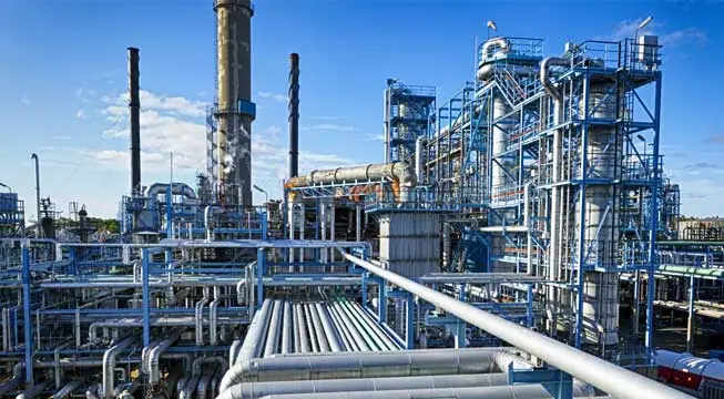
Refining & Petrochemical

Expand visibility and control of your refinery or petrochemical processing facility without expensive renovations or redesigns. And do it with your current gauges and hardware. SignalFire telemetry devices are designed to work in harsh chemical environments and meet the strictest safety and security standards
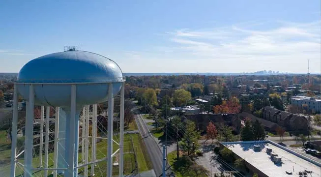
Utilities

No matter the size of your service map, monitoring remote assets ensures efficiency and keeps your operation in compliance. That’s how SignalFire devices can really help, offering the most affordable and effective monitoring solution that will monitor liquid, gas, electricity, and other assets.

Document Center

Browse all documentation pertaining to SignalFire products.

Cloud Setup

Have a RANGER? Set up your Cloud account here.
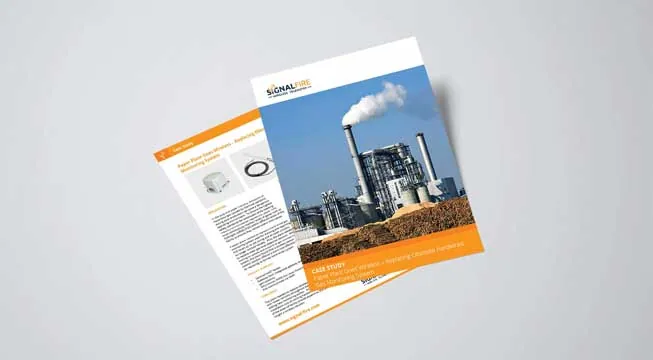
Case Studies

Explore the diverse applications of SignalFire Wireless Telemetry Systems across different industries.

Brochures

Access our latest brochures to explore comprehensive information about our products and services.

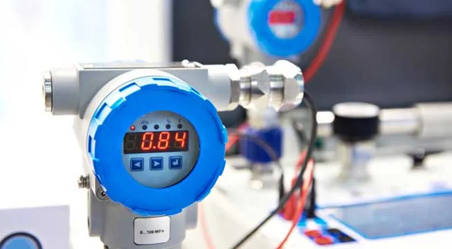
Commonly Supported Sensors

Easily find the sensors that are compatible with our systems on this dedicated page.

Photos

Explore a comprehensive collection of images showcasing our products, installations, and real-world applications.
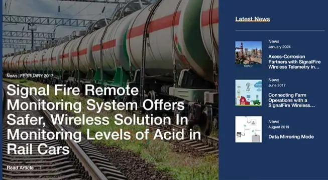
News & Articles

Stay up to date with the latest content from SignalFire.
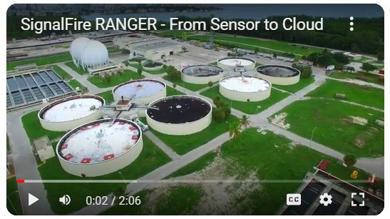
Videos

Explore our video library.

Software Downloads

Get access to the RANGER and SignalFire Toolkit Software.

Contact Tech Support

Videos

In this video, we walk through how to configure the MIOM module for Modbus mode using the SignalFire ToolKit. This step-by-step tutorial shows you how to properly set up the MIOM module so it can communicate with a SignalFire gateway and integrate wired Modbus devices into your system.

You’ll learn:

-  What the MIOM module is used for
- Why switching the MIOM to Modbus mode is required
- How to connect the USB 4-pin cable
- How to use the SignalFire ToolKit software
- Key configuration settings to verify before deployment

This setup is essential when integrating wired instrumentation into a SignalFire wireless network or gateway. Whether you’re commissioning a new system or troubleshooting an existing installation, this video will help ensure your MIOM module is configured correctly.

- Download the SignalFire ToolKit: https://www.signal-fire.com/signalfire-toolkit-software/
- Learn more about SignalFire Wireless Telemetry solutions at: https://www.signal-fire.com

0:00 Introduction to the tutorial
0:10 Purpose of changing MultiIO firmware mode
0:22 When to use MultiIO with Ranger or PATRIoT Gateway
0:38 Connecting the MultiIO module to the ToolKit
0:48 Auto-detecting the module in SignalFire ToolKit
0:53 Identifying the current firmware mode
1:09 Selecting Standalone Modbus MultiIO firmware
1:20 Starting the firmware upgrade
1:26 Power requirements during the upgrade
1:39 Upgrade completion and reboot confirmation
1:50 Final recap and conclusion

In this video, we walk through how to configure the MIOM module for Modbus mode using the SignalFire ToolKit. This step-by-step tutorial shows you how to properly set up the MIOM module so it can communicate with a SignalFire gateway and integrate wired Modbus devices into your system.

You’ll learn:

– What the MIOM module is used for
– Why switching the MIOM to Modbus mode is required
– How to connect the USB 4-pin cable
– How to use the SignalFire ToolKit software
– Key configuration settings to verify before deployment

This setup is essential when integrating wired instrumentation into a SignalFire wireless network or gateway. Whether you’re commissioning a new system or troubleshooting an existing installation, this video will help ensure your MIOM module is configured correctly.

– Download the SignalFire ToolKit: https://www.signal-fire.com/signalfire-toolkit-software/
– Learn more about SignalFire Wireless Telemetry solutions at: https://www.signal-fire.com

0:00 Introduction to the tutorial
0:10 Purpose of changing MultiIO firmware mode
0:22 When to use MultiIO with Ranger or PATRIoT Gateway
0:38 Connecting the MultiIO module to the ToolKit
0:48 Auto-detecting the module in SignalFire ToolKit
0:53 Identifying the current firmware mode
1:09 Selecting Standalone Modbus MultiIO firmware
1:20 Starting the firmware upgrade
1:26 Power requirements during the upgrade
1:39 Upgrade completion and reboot confirmation
1:50 Final recap and conclusion

1 0

YouTube Video VVVaNWQ3dEJfVUpNYVphU1MtSTF6UVl3Lkw4T0xYRkNrbmdn

How to Configure the MIOM Module for Modbus Mode | SignalFire Toolkit Setup Guide

SignalFireTelemetry January 16, 2026 12:21 PM

In this video, we provide an introduction to the SignalFire DIN RANGER and walk through the basic setup and configuration process. You’ll learn how the DIN RANGER fits into the SignalFire Wireless Telemetry ecosystem and how to quickly get it up and running for reliable data transmission.

This tutorial covers:

- What the SignalFire DIN RANGER is and where it’s used
- Basic hardware overview
- Initial setup and configuration steps
- How the DIN RANGER integrates with SignalFire Wireless Telemetry gateways and wireless networks

The DIN RANGER is designed for industrial monitoring applications where reliability, flexibility, and long-range wireless communication are critical. Whether you’re new to SignalFire Wireless Telemetry products or looking for a quick refresher, this video will help you confidently deploy a DIN RANGER in the field.

- Learn more about SignalFire Wireless Telemetry solutions at: https://www.signal-fire.com

0:00 Introduction to Signal Fire & Video Overview
0:12 What Is the DIN RANGER and RANGER Product Family
0:36 DIN RANGER Use Cases & Panel Mount Applications
0:48 Connecting Wired Devices & IO Modules
0:59 Cloud Connectivity Options & SIM Card Overview
1:13 Power Requirements & Startup Indicators
1:29 Claiming the DIN RANGER in Signal Fire Cloud
2:05 Adding a Device Using the Serial Number
2:30 Cloud Handshaking & Device Activation
2:52 Built-In Inputs and Outputs Overview
3:19 Modbus RTU Data Collection Explained
3:30 Testing Digital Inputs in the Cloud
3:51 Forcing Measurements & Reporting Data
4:17 State Change Reporting for Digital Inputs
4:29 Summary of DIN RANGER Setup Process
4:55 Additional Resources & Where to Learn More

In this video, we provide an introduction to the SignalFire DIN RANGER and walk through the basic setup and configuration process. You’ll learn how the DIN RANGER fits into the SignalFire Wireless Telemetry ecosystem and how to quickly get it up and running for reliable data transmission.

This tutorial covers:

– What the SignalFire DIN RANGER is and where it’s used
– Basic hardware overview
– Initial setup and configuration steps
– How the DIN RANGER integrates with SignalFire Wireless Telemetry gateways and wireless networks

The DIN RANGER is designed for industrial monitoring applications where reliability, flexibility, and long-range wireless communication are critical. Whether you’re new to SignalFire Wireless Telemetry products or looking for a quick refresher, this video will help you confidently deploy a DIN RANGER in the field.

– Learn more about SignalFire Wireless Telemetry solutions at: https://www.signal-fire.com

0:00 Introduction to Signal Fire & Video Overview
0:12 What Is the DIN RANGER and RANGER Product Family
0:36 DIN RANGER Use Cases & Panel Mount Applications
0:48 Connecting Wired Devices & IO Modules
0:59 Cloud Connectivity Options & SIM Card Overview
1:13 Power Requirements & Startup Indicators
1:29 Claiming the DIN RANGER in Signal Fire Cloud
2:05 Adding a Device Using the Serial Number
2:30 Cloud Handshaking & Device Activation
2:52 Built-In Inputs and Outputs Overview
3:19 Modbus RTU Data Collection Explained
3:30 Testing Digital Inputs in the Cloud
3:51 Forcing Measurements & Reporting Data
4:17 State Change Reporting for Digital Inputs
4:29 Summary of DIN RANGER Setup Process
4:55 Additional Resources & Where to Learn More

2 0

YouTube Video VVVaNWQ3dEJfVUpNYVphU1MtSTF6UVl3LlQ3MVJHQXRzQlhj

SignalFire DIN RANGER Overview & Basic Setup | Wireless Telemetry Node Configuration

SignalFireTelemetry January 16, 2026 12:11 PM

Learn how to configure and deploy the SignalFire RANGER AirQ in this step-by-step basic setup tutorial. This video covers the essential hardware connections, configuration steps, and best practices for getting your RANGER AirQ up and running quickly and reliably.

You’ll see how the RANGER AirQ is prepared for deployment, how wireless communication is established, and what to verify to ensure accurate, dependable air quality data in the field.

This tutorial is ideal for:
• Field technicians
• Instrumentation and controls professionals
• Environmental and emissions monitoring teams
• SCADA and industrial telemetry users

Whether you’re installing a new system or reviewing the basics, this video provides a solid foundation for deploying the SignalFire RANGER AirQ for remote air quality monitoring applications.

- Subscribe for more SignalFire setup guides, product walkthroughs, and application tutorials.

0:00 Introduction to RANGER AirQ
0:12 What Is RANGER AirQ & How It Works
0:22 Methane Gas Measurement Overview
0:36 Configuration Options Overview (Toolkit vs Cloud)
1:00 Connecting RANGER AirQ to a PC
1:18 Launching the RANGER Toolkit
1:31 Naming Your RANGER AirQ Device
1:53 Emissions Mode vs Continuous Mode Explained
2:37 Battery Life Comparison by Mode
3:10 Setting Thresholds & Report by Exception
3:34 Viewing Live Measurements & Diagnostics
3:51 Additional Sensor Data (Temp, Pressure, Humidity)
4:11 Configuration Complete Using RANGER Toolkit
4:17 Configuring RANGER AirQ via SignalFire Cloud
4:36 Viewing Gas Data in the Cloud Dashboard
4:48 Changing Modes & Thresholds in the Cloud
5:28 Confirming Configuration Updates
5:35 Testing with Methane Calibration Gas
5:54 Forcing a Report from the Cloud
6:07 RANGER AirQ Summary & Key Capabilities
6:24 Additional Resources & Documentation

Learn how to configure and deploy the SignalFire RANGER AirQ in this step-by-step basic setup tutorial. This video covers the essential hardware connections, configuration steps, and best practices for getting your RANGER AirQ up and running quickly and reliably.

You’ll see how the RANGER AirQ is prepared for deployment, how wireless communication is established, and what to verify to ensure accurate, dependable air quality data in the field.

This tutorial is ideal for:
• Field technicians
• Instrumentation and controls professionals
• Environmental and emissions monitoring teams
• SCADA and industrial telemetry users

Whether you’re installing a new system or reviewing the basics, this video provides a solid foundation for deploying the SignalFire RANGER AirQ for remote air quality monitoring applications.

– Subscribe for more SignalFire setup guides, product walkthroughs, and application tutorials.

0:00 Introduction to RANGER AirQ
0:12 What Is RANGER AirQ & How It Works
0:22 Methane Gas Measurement Overview
0:36 Configuration Options Overview (Toolkit vs Cloud)
1:00 Connecting RANGER AirQ to a PC
1:18 Launching the RANGER Toolkit
1:31 Naming Your RANGER AirQ Device
1:53 Emissions Mode vs Continuous Mode Explained
2:37 Battery Life Comparison by Mode
3:10 Setting Thresholds & Report by Exception
3:34 Viewing Live Measurements & Diagnostics
3:51 Additional Sensor Data (Temp, Pressure, Humidity)
4:11 Configuration Complete Using RANGER Toolkit
4:17 Configuring RANGER AirQ via SignalFire Cloud
4:36 Viewing Gas Data in the Cloud Dashboard
4:48 Changing Modes & Thresholds in the Cloud
5:28 Confirming Configuration Updates
5:35 Testing with Methane Calibration Gas
5:54 Forcing a Report from the Cloud
6:07 RANGER AirQ Summary & Key Capabilities
6:24 Additional Resources & Documentation

1 0

YouTube Video VVVaNWQ3dEJfVUpNYVphU1MtSTF6UVl3LmVjbFg3VE9uU3VV

SignalFire RANGER AirQ Basic Setup | Wireless Air Quality Monitoring Tutorial

SignalFireTelemetry January 16, 2026 12:04 PM

Learn how to perform a basic setup of the AirQ Scout using the PATRIoT Gateway in this step-by-step tutorial from SignalFire Telemetry.

In this video, we walk through how to power, connect, and configure the AirQ Scout to communicate wirelessly with the PATRIoT Gateway using SignalFire’s long-range 900 MHz technology. You’ll see how the PATRIoT Gateway aggregates wireless sensor data and delivers it into SCADA systems, the SignalFire Cloud, or third-party monitoring platforms.

This tutorial is ideal for system integrators, instrumentation technicians, and engineers looking to quickly deploy reliable wireless gas and environmental monitoring solutions.

What you’ll learn:

- AirQ Scout overview and use case
- Basic AirQ Scout setup and configuration
- How the AirQ Scout communicates with the PATRIoT Gateway
- Power and connectivity requirements
- Best practices for reliable wireless telemetry

Whether you’re deploying a new system or learning the fundamentals, this video helps simplify wireless sensor integration with the PATRIoT Gateway.

👉 Learn more at: https://signal-fire.com

0:00 – Introduction & Video Overview
0:20 – AirQ Scout + PATRIoT Gateway Configuration Overview
0:24 – Preconfigured PATRIoT Gateway Radio Settings
0:33 – Required Tools & Software Setup
0:48 – Connecting the AirQ Scout to the SignalFire ToolKit
1:05 – Matching AirQ Scout Radio Settings to the Gateway
1:25 – Applying Settings & Establishing Wireless Communication
1:44 – Forcing a Check-In & Connection Status
1:56 – Avoiding Signal Interference During Setup
2:14 – Wireless Connection Confirmed
2:20 – Gas Measurement Configuration Overview
2:23 – Emissions Mode vs Continuous Mode Explained
2:38 – Battery Life Comparison by Mode
3:02 – Setting Gas Concentration Thresholds
3:24 – Adaptive Reporting Cadence Based on Thresholds
3:51 – Final Configuration Summary

Learn how to perform a basic setup of the AirQ Scout using the PATRIoT Gateway in this step-by-step tutorial from SignalFire Telemetry.

In this video, we walk through how to power, connect, and configure the AirQ Scout to communicate wirelessly with the PATRIoT Gateway using SignalFire’s long-range 900 MHz technology. You’ll see how the PATRIoT Gateway aggregates wireless sensor data and delivers it into SCADA systems, the SignalFire Cloud, or third-party monitoring platforms.

This tutorial is ideal for system integrators, instrumentation technicians, and engineers looking to quickly deploy reliable wireless gas and environmental monitoring solutions.

What you’ll learn:

– AirQ Scout overview and use case
– Basic AirQ Scout setup and configuration
– How the AirQ Scout communicates with the PATRIoT Gateway
– Power and connectivity requirements
– Best practices for reliable wireless telemetry

Whether you’re deploying a new system or learning the fundamentals, this video helps simplify wireless sensor integration with the PATRIoT Gateway.

👉 Learn more at: https://signal-fire.com

0:00 – Introduction & Video Overview
0:20 – AirQ Scout + PATRIoT Gateway Configuration Overview
0:24 – Preconfigured PATRIoT Gateway Radio Settings
0:33 – Required Tools & Software Setup
0:48 – Connecting the AirQ Scout to the SignalFire ToolKit
1:05 – Matching AirQ Scout Radio Settings to the Gateway
1:25 – Applying Settings & Establishing Wireless Communication
1:44 – Forcing a Check-In & Connection Status
1:56 – Avoiding Signal Interference During Setup
2:14 – Wireless Connection Confirmed
2:20 – Gas Measurement Configuration Overview
2:23 – Emissions Mode vs Continuous Mode Explained
2:38 – Battery Life Comparison by Mode
3:02 – Setting Gas Concentration Thresholds
3:24 – Adaptive Reporting Cadence Based on Thresholds
3:51 – Final Configuration Summary

1 0

YouTube Video VVVaNWQ3dEJfVUpNYVphU1MtSTF6UVl3LnBTSWNYWFpOWmFZ

AirQ Scout Basic Setup with the PATRIoT Gateway | Wireless Sensor Integration Tutorial

SignalFireTelemetry January 16, 2026 11:48 AM

Discover the SignalFire AirQ Product Family, a powerful lineup of wireless gas and air quality monitoring solutions designed for industrial and environmental applications.

In this video, we introduce the AirQ family and explain how these long-range, low-power wireless devices deliver reliable measurements from remote and challenging locations. Built for harsh environments, AirQ sensors integrate seamlessly with SignalFire’s wireless telemetry network, enabling real-time data visibility, improved safety, and simplified deployment—without trenching or expensive infrastructure.

Whether you’re monitoring gas detection, air quality, or environmental conditions, the AirQ Product Family provides a scalable, cost-effective solution trusted across oil & gas, water & wastewater, chemical processing, and industrial facilities.

- Long-range 900 MHz wireless communication
- Battery-powered, low-maintenance design
- Seamless integration with SignalFire networks and gateways
- Ideal for hazardous and remote locations

Learn how the SignalFire AirQ Product Family helps you monitor smarter, deploy faster, and operate more efficiently.

- Visit https://www.signal-fire.com/ to learn more.

0:00 – Introduction to the SignalFire AirQ Product Family
0:15 – Wireless Gas Monitoring Overview
0:27 – AirQ Scout (900 MHz Wireless Technology)
0:45 – Ranger AirQ (Cellular LTE-M / NB-IoT)
1:02 – Gas Types Measured: Methane & H₂S
1:09 – Low-Power Design & Long Battery Life
1:24 – Measurement Modes: Continuous vs Emissions
1:54 – Smart Threshold Detection & Accelerated Sampling
2:15 – Sensor Reliability & Low Maintenance Benefits
2:34 – Additional Measurements (Temp, Humidity, Pressure)
2:48 – Communication Range & Cloud Integration
3:02 – Summary & Next Steps

Discover the SignalFire AirQ Product Family, a powerful lineup of wireless gas and air quality monitoring solutions designed for industrial and environmental applications.

In this video, we introduce the AirQ family and explain how these long-range, low-power wireless devices deliver reliable measurements from remote and challenging locations. Built for harsh environments, AirQ sensors integrate seamlessly with SignalFire’s wireless telemetry network, enabling real-time data visibility, improved safety, and simplified deployment—without trenching or expensive infrastructure.

Whether you’re monitoring gas detection, air quality, or environmental conditions, the AirQ Product Family provides a scalable, cost-effective solution trusted across oil & gas, water & wastewater, chemical processing, and industrial facilities.

– Long-range 900 MHz wireless communication
– Battery-powered, low-maintenance design
– Seamless integration with SignalFire networks and gateways
– Ideal for hazardous and remote locations

Learn how the SignalFire AirQ Product Family helps you monitor smarter, deploy faster, and operate more efficiently.

– Visit https://www.signal-fire.com/ to learn more.

0:00 – Introduction to the SignalFire AirQ Product Family
0:15 – Wireless Gas Monitoring Overview
0:27 – AirQ Scout (900 MHz Wireless Technology)
0:45 – Ranger AirQ (Cellular LTE-M / NB-IoT)
1:02 – Gas Types Measured: Methane & H₂S
1:09 – Low-Power Design & Long Battery Life
1:24 – Measurement Modes: Continuous vs Emissions
1:54 – Smart Threshold Detection & Accelerated Sampling
2:15 – Sensor Reliability & Low Maintenance Benefits
2:34 – Additional Measurements (Temp, Humidity, Pressure)
2:48 – Communication Range & Cloud Integration
3:02 – Summary & Next Steps

2 0

YouTube Video VVVaNWQ3dEJfVUpNYVphU1MtSTF6UVl3LlBuWE5fc25aNHpB

SignalFire AirQ Product Family Overview | Wireless Gas & Air Quality Monitoring Solutions

SignalFireTelemetry January 16, 2026 11:18 AM

Learn how to complete a basic MIOM setup using the PATRIoT Gateway from SignalFire Wireless Telemetry. In this step-by-step tutorial, we walk through the essentials of configuring the MIOM module and integrating it with the PATRIoT Gateway for reliable wireless and wired signal aggregation.

The PATRIoT Gateway acts as a powerful protocol aggregator, enabling seamless data collection from SignalFire wireless nodes and wired I/O modules into your SCADA system, cloud platform, or monitoring software. This video is ideal for technicians, system integrators, and engineers looking to quickly deploy and configure SignalFire equipment in industrial environments.

What you’ll learn in this video:

- Overview of the PATRIoT Gateway and MIOM functionality
- Basic MIOM wiring and setup concepts
- How the PATRIoT Gateway aggregates wired and wireless signals
- Best practices for initial configuration and deployment

Whether you’re setting up a new system or expanding an existing one, this video provides a solid foundation for working with the PATRIoT Gateway and MIOM modules.

- Learn more about SignalFire solutions at: https://www.signal-fire.com

0:00 – Introduction & Video Overview
0:09 – PATRIoT Gateway Wired Device Integration Overview
0:31 – MIOM vs Output Module Options
0:38 – Preconditioning the MIOM for Modbus Communication
0:45 – Connecting the MIOM via USB & Using SignalFire ToolKit
0:56 – Setting the MIOM to Modbus Mode (Critical Step)
1:10 – Wiring Modbus A/B Connections to the PATRIoT Gateway
1:33 – Powering the MIOM & Verifying Status LEDs
1:46 – Opening the PATRIoT Gateway ToolKit Module
1:58 – Configuring the Serial Port Settings
2:26 – Selecting RS-485 & Modbus RTU Client Mode
2:54 – Matching Baud Rate & UART Settings
3:02 – Applying Serial Port Configuration
3:10 – Setting Up Modbus RTU Client Polling
3:30 – Using the Address Picker for MIOM Registers
3:42 – Selecting Multi-IO Module Registers
3:56 – Choosing Digital Input Counters & States
4:15 – Assigning the Modbus ID to the MIOM
4:41 – Writing Register Settings to the Gateway
4:46 – Verifying Data Polling from the MIOM
4:58 – Sending Data to SCADA or Cloud Systems
5:26 – Summary & Key Benefits of Wired Integration
5:49 – Additional Resources & Closing

Learn how to complete a basic MIOM setup using the PATRIoT Gateway from SignalFire Wireless Telemetry. In this step-by-step tutorial, we walk through the essentials of configuring the MIOM module and integrating it with the PATRIoT Gateway for reliable wireless and wired signal aggregation.

The PATRIoT Gateway acts as a powerful protocol aggregator, enabling seamless data collection from SignalFire wireless nodes and wired I/O modules into your SCADA system, cloud platform, or monitoring software. This video is ideal for technicians, system integrators, and engineers looking to quickly deploy and configure SignalFire equipment in industrial environments.

What you’ll learn in this video:

– Overview of the PATRIoT Gateway and MIOM functionality
– Basic MIOM wiring and setup concepts
– How the PATRIoT Gateway aggregates wired and wireless signals
– Best practices for initial configuration and deployment

Whether you’re setting up a new system or expanding an existing one, this video provides a solid foundation for working with the PATRIoT Gateway and MIOM modules.

– Learn more about SignalFire solutions at: https://www.signal-fire.com

0:00 – Introduction & Video Overview
0:09 – PATRIoT Gateway Wired Device Integration Overview
0:31 – MIOM vs Output Module Options
0:38 – Preconditioning the MIOM for Modbus Communication
0:45 – Connecting the MIOM via USB & Using SignalFire ToolKit
0:56 – Setting the MIOM to Modbus Mode (Critical Step)
1:10 – Wiring Modbus A/B Connections to the PATRIoT Gateway
1:33 – Powering the MIOM & Verifying Status LEDs
1:46 – Opening the PATRIoT Gateway ToolKit Module
1:58 – Configuring the Serial Port Settings
2:26 – Selecting RS-485 & Modbus RTU Client Mode
2:54 – Matching Baud Rate & UART Settings
3:02 – Applying Serial Port Configuration
3:10 – Setting Up Modbus RTU Client Polling
3:30 – Using the Address Picker for MIOM Registers
3:42 – Selecting Multi-IO Module Registers
3:56 – Choosing Digital Input Counters & States
4:15 – Assigning the Modbus ID to the MIOM
4:41 – Writing Register Settings to the Gateway
4:46 – Verifying Data Polling from the MIOM
4:58 – Sending Data to SCADA or Cloud Systems
5:26 – Summary & Key Benefits of Wired Integration
5:49 – Additional Resources & Closing

2 0

YouTube Video VVVaNWQ3dEJfVUpNYVphU1MtSTF6UVl3LmVOLXVhRzFmb2dj

PATRIoT Gateway MIOM Basic Setup | SignalFire Wireless Telemetry Configuration Tutorial

SignalFireTelemetry January 16, 2026 11:09 AM

Learn how to configure MQTT on the SignalFire PATRIoT Gateway in this step-by-step tutorial.

This video walks through the basic MQTT setup, showing how to publish telemetry data from SignalFire wireless and wired devices to your broker or cloud platform.

The PATRIoT Gateway is a powerful protocol aggregator that supports MQTT, Modbus TCP, Modbus Serial, and EtherNet/IP—making it easy to integrate field data into SCADA systems, cloud dashboards, or custom applications.

What you’ll learn in this video:

- What MQTT is and why it’s used in industrial telemetry
- How to enable and configure MQTT on the PATRIoT Gateway
- Publishing measurement data to an MQTT broker
- Common setup tips and best practices
- How MQTT fits into SignalFire’s wireless telemetry ecosystem

This tutorial is ideal for system integrators, controls engineers, and operators looking to move data securely and efficiently using MQTT.

- Learn more about the PATRIoT Gateway and SignalFire Wireless Telemetry:
https://www.signal-fire.com

- Request a demo or talk to an expert: https://www.signal-fire.com/contact

If this video helped you, like, subscribe, and share with your team.

0:00 Introduction to MQTT on the PATRIoT Gateway
0:24 How Data Gets Into the PATRIoT Gateway
0:48 Using Ethernet to Send MQTT Data
1:13 Local SCADA vs Cloud vs Satellite Connectivity
1:45 Overview of Configuration Using SignalFire ToolKit
1:54 Prerequisites: Devices Connected to the Gateway
2:06 Configuring Network Settings (DHCP vs Static IP)
2:53 Navigating to the MQTT Configuration Tab
3:01 Enabling the MQTT Client
3:30 Verifying MQTT Connection Status
3:54 Using SignalFire Cloud vs Custom MQTT Broker
4:11 Understanding Sparkplug and MQTT Topics
4:18 Mapping Measurements with Sparkplug
4:48 Selecting Devices and Registers
5:14 Choosing Measurements to Publish
5:32 Writing Sparkplug Tags to the PATRIoT Gateway
5:46 MQTT Topics Ready for Consumption
6:00 Summary and Next Steps

Learn how to configure MQTT on the SignalFire PATRIoT Gateway in this step-by-step tutorial.

This video walks through the basic MQTT setup, showing how to publish telemetry data from SignalFire wireless and wired devices to your broker or cloud platform.

The PATRIoT Gateway is a powerful protocol aggregator that supports MQTT, Modbus TCP, Modbus Serial, and EtherNet/IP—making it easy to integrate field data into SCADA systems, cloud dashboards, or custom applications.

What you’ll learn in this video:

– What MQTT is and why it’s used in industrial telemetry
– How to enable and configure MQTT on the PATRIoT Gateway
– Publishing measurement data to an MQTT broker
– Common setup tips and best practices
– How MQTT fits into SignalFire’s wireless telemetry ecosystem

This tutorial is ideal for system integrators, controls engineers, and operators looking to move data securely and efficiently using MQTT.

– Learn more about the PATRIoT Gateway and SignalFire wireless telemetry:
https://www.signal-fire.com

– Request a demo or talk to an expert: https://www.signal-fire.com/contact

If this video helped you, like, subscribe, and share with your team.

0:00 Introduction to MQTT on the PATRIoT Gateway
0:24 How Data Gets Into the PATRIoT Gateway
0:48 Using Ethernet to Send MQTT Data
1:13 Local SCADA vs Cloud vs Satellite Connectivity
1:45 Overview of Configuration Using SignalFire ToolKit
1:54 Prerequisites: Devices Connected to the Gateway
2:06 Configuring Network Settings (DHCP vs Static IP)
2:53 Navigating to the MQTT Configuration Tab
3:01 Enabling the MQTT Client
3:30 Verifying MQTT Connection Status
3:54 Using SignalFire Cloud vs Custom MQTT Broker
4:11 Understanding Sparkplug and MQTT Topics
4:18 Mapping Measurements with Sparkplug
4:48 Selecting Devices and Registers
5:14 Choosing Measurements to Publish
5:32 Writing Sparkplug Tags to the PATRIoT Gateway
5:46 MQTT Topics Ready for Consumption
6:00 Summary and Next Steps

1 0

YouTube Video VVVaNWQ3dEJfVUpNYVphU1MtSTF6UVl3LktPZ1VWTkpmOEZR

SignalFire PATRIoT Gateway MQTT Setup | Industrial MQTT Configuration Tutorial

SignalFireTelemetry January 16, 2026 10:57 AM

The SignalFire PATRIoT Gateway is a powerful and flexible 900 MHz wireless telemetry gateway designed for reliable data collection in industrial environments.

In this video, we walk through the basic setup and overview of the PATRIoT Gateway, including how it serves as a central hub for connecting wireless field devices, collecting sensor data, and transmitting measurements to control systems, cloud platforms, or SCADA.

The PATRIoT Gateway is ideal for applications such as:

- Oil & gas production monitoring
- Water and wastewater systems
- Tank level and flow monitoring
- Remote asset monitoring
- Industrial IoT (IIoT) deployments

Key features covered in this video:
✔ 900 MHz long-range wireless communication
✔ Seamless integration with SignalFire wireless nodes
✔ Secure and reliable data transmission
✔ Industrial-grade design for harsh environments
✔ Flexible connectivity for SCADA, PLCs, and cloud systems

Whether you’re new to SignalFire or looking to expand your wireless telemetry network, this video provides a solid foundation for understanding how the PATRIoT Gateway fits into your system architecture.

- Learn more about SignalFire wireless telemetry: https://signal-fire.com

- Access support and documentation: https://ai.signal-fire.com

Subscribe for more videos on industrial wireless solutions, setup guides, and best practices.

00:00 – Introduction & Video Overview
Overview of connecting a SignalFire PATRIOT Gateway to a wireless node

00:09 – PATRIOT Gateway & AirQ Scout Overview
Introduction to the PATRIOT Gateway and AirQ Scout 900 MHz wireless device

00:27 – Power Requirements for the PATRIOT Gateway
Explaining the 10–30 VDC power supply needed for the gateway

00:39 – MIM Module & Signal Aggregation
How the PATRIOT Gateway aggregates wired and wireless signals using the MIM module

00:58 – Required Software: SignalFire Toolkit
Overview of the SignalFire Toolkit software and where to download it

01:12 – Connecting the Gateway to a Computer (USB-C)
Using a USB-C connection to configure the PATRIOT Gateway

01:19 – Alternate Configuration Method (Ethernet / RJ45)
Configuring the PATRIOT Gateway using the RJ45 Ethernet port

The SignalFire PATRIoT Gateway is a powerful and flexible 900 MHz wireless telemetry gateway designed for reliable data collection in industrial environments.

In this video, we walk through the basic setup and overview of the PATRIoT Gateway, including how it serves as a central hub for connecting wireless field devices, collecting sensor data, and transmitting measurements to control systems, cloud platforms, or SCADA.

The PATRIoT Gateway is ideal for applications such as:

– Oil & gas production monitoring
– Water and wastewater systems
– Tank level and flow monitoring
– Remote asset monitoring
– Industrial IoT (IIoT) deployments

Key features covered in this video:
✔ 900 MHz long-range wireless communication
✔ Seamless integration with SignalFire wireless nodes
✔ Secure and reliable data transmission
✔ Industrial-grade design for harsh environments
✔ Flexible connectivity for SCADA, PLCs, and cloud systems

Whether you’re new to SignalFire or looking to expand your wireless telemetry network, this video provides a solid foundation for understanding how the PATRIoT Gateway fits into your system architecture.

– Learn more about SignalFire wireless telemetry: https://signal-fire.com

– Access support and documentation: https://ai.signal-fire.com

Subscribe for more videos on industrial wireless solutions, setup guides, and best practices.

00:00 – Introduction & Video Overview
Overview of connecting a SignalFire PATRIOT Gateway to a wireless node

00:09 – PATRIOT Gateway & AirQ Scout Overview
Introduction to the PATRIOT Gateway and AirQ Scout 900 MHz wireless device

00:27 – Power Requirements for the PATRIOT Gateway
Explaining the 10–30 VDC power supply needed for the gateway

00:39 – MIM Module & Signal Aggregation
How the PATRIOT Gateway aggregates wired and wireless signals using the MIM module

00:58 – Required Software: SignalFire Toolkit
Overview of the SignalFire Toolkit software and where to download it

01:12 – Connecting the Gateway to a Computer (USB-C)
Using a USB-C connection to configure the PATRIOT Gateway

01:19 – Alternate Configuration Method (Ethernet / RJ45)
Configuring the PATRIOT Gateway using the RJ45 Ethernet port

4 0

YouTube Video VVVaNWQ3dEJfVUpNYVphU1MtSTF6UVl3LnlTMXBZbGN0dmlj

SignalFire PATRIOT Gateway | 900 MHz Wireless Telemetry Gateway Overview & Setup

SignalFireTelemetry January 15, 2026 3:50 PM

SignalFire’s PATRIoT Gateway is a powerful industrial wireless gateway designed for reliable, long-range data collection and seamless integration with modern control systems and cloud platforms.

In this video, we introduce the SignalFire PATRIoT Gateway and walk through how it serves as the backbone of a robust wireless telemetry network. Designed for demanding industrial environments, the PATRIoT Gateway collects data from SignalFire wireless nodes and delivers it securely to PLCs, SCADA systems, and cloud-based monitoring platforms.

Key benefits of the PATRIoT Gateway include:

- Reliable long-range wireless communication
- Industrial-grade performance for harsh environments
- Easy integration with SCADA, PLC, and cloud systems
- Secure and scalable wireless telemetry architecture
- Ideal for oil & gas, water & wastewater, chemical, mining, and industrial automation applications

Whether you’re modernizing legacy infrastructure or deploying a new wireless monitoring system, the SignalFire PATRIoT Gateway provides the flexibility and reliability needed for mission-critical data transmission.

👉 Learn more about SignalFire wireless telemetry solutions: https://www.signal-fire.com

👉 Request a demo or talk to an expert: https://www.signal-fire.com/contact

00:00 Introduction to the SignalFire Patriot Gateway
00:14 What Is the Patriot Gateway?
00:20 Connecting Wireless & Wired Devices to SCADA and Cloud
00:34 Supported Protocols: Modbus, Ethernet/IP, MQTT Sparkplug
00:46 Aggregating 900 MHz Wireless and Wired I/O Data
01:09 Ultra-Low Power Design & Solar-Powered Systems
01:20 Scalability: From Small Systems to Thousands of Tags
01:30 Use Cases: Shorter Cable Runs, Local Automation, Expansion
01:40 Modernizing Industrial Monitoring with Patriot Gateway
01:44 Learn More & Additional Setup Videos

SignalFire’s PATRIoT Gateway is a powerful industrial wireless gateway designed for reliable, long-range data collection and seamless integration with modern control systems and cloud platforms.

In this video, we introduce the SignalFire PATRIoT Gateway and walk through how it serves as the backbone of a robust wireless telemetry network. Designed for demanding industrial environments, the PATRIoT Gateway collects data from SignalFire wireless nodes and delivers it securely to PLCs, SCADA systems, and cloud-based monitoring platforms.

Key benefits of the PATRIoT Gateway include:

– Reliable long-range wireless communication
– Industrial-grade performance for harsh environments
– Easy integration with SCADA, PLC, and cloud systems
– Secure and scalable wireless telemetry architecture
– Ideal for oil & gas, water & wastewater, chemical, mining, and industrial automation applications

Whether you’re modernizing legacy infrastructure or deploying a new wireless monitoring system, the SignalFire PATRIoT Gateway provides the flexibility and reliability needed for mission-critical data transmission.

👉 Learn more about SignalFire wireless telemetry solutions: https://www.signal-fire.com

👉 Request a demo or talk to an expert: https://www.signal-fire.com/contact

00:00 Introduction to the SignalFire Patriot Gateway
00:14 What Is the Patriot Gateway?
00:20 Connecting Wireless & Wired Devices to SCADA and Cloud
00:34 Supported Protocols: Modbus, Ethernet/IP, MQTT Sparkplug
00:46 Aggregating 900 MHz Wireless and Wired I/O Data
01:09 Ultra-Low Power Design & Solar-Powered Systems
01:20 Scalability: From Small Systems to Thousands of Tags
01:30 Use Cases: Shorter Cable Runs, Local Automation, Expansion
01:40 Modernizing Industrial Monitoring with Patriot Gateway
01:44 Learn More & Additional Setup Videos

3 1

YouTube Video VVVaNWQ3dEJfVUpNYVphU1MtSTF6UVl3Li16c0t2MDBKUXJ3

SignalFire PATRIoT Gateway | Programmable & Telemetry Ready IoT Gateway

SignalFireTelemetry January 15, 2026 12:56 PM