

Case Study |
7.11.24
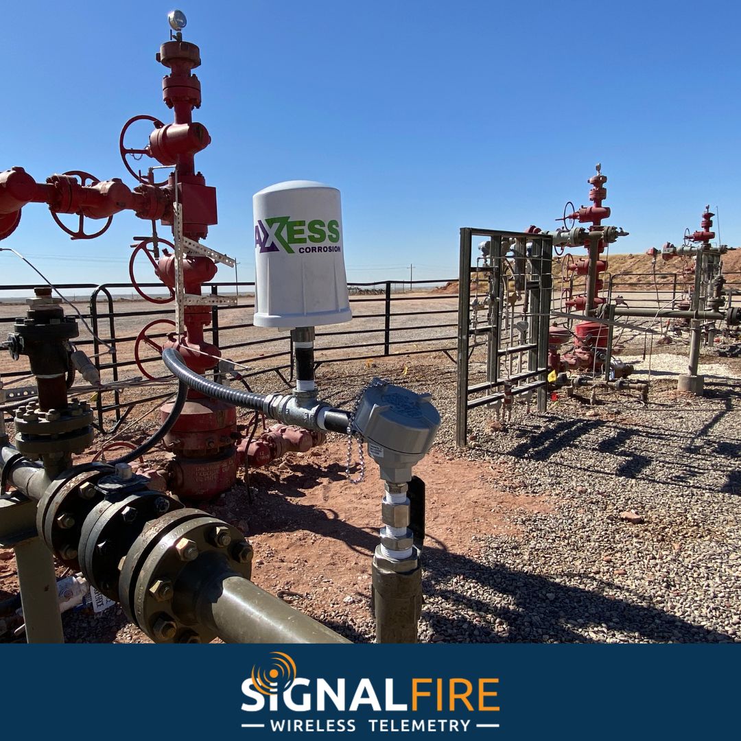
SignalFire Telemetry products connect you with crucial product and hardware data at any of your oil and gas operation sites—whether it’s a pump, pipeline, or storage tank.

SignalFire Telemetry devices install anywhere water asset monitoring is needed, whether it’s for collection purposes, treatment, or delivery.

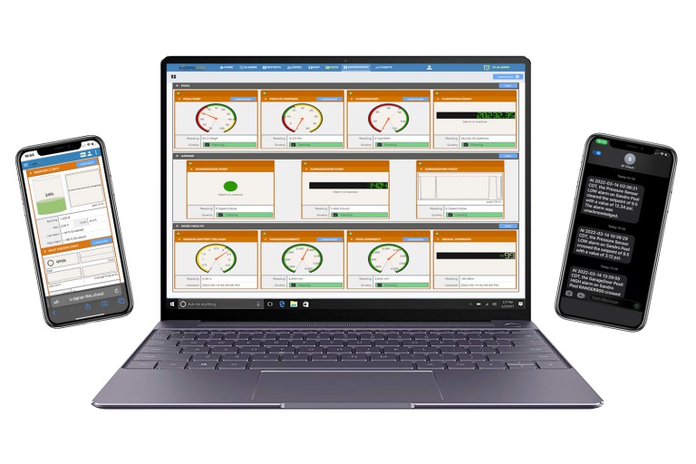
SignalFire Telemetry devices can monitor key assets and can do it affordably, without any renovation or high-priced engineering costs. They install easily with no required cable or additional power. The data is available on your phone or computer and the cloud service can even output to your corporate system to integrate with the rest of your data and keep your operation running.

SignalFire Telemetry devices can monitor and manage water supplies and additives throughout the property, helping you avoid catastrophic shortages and keep your irrigation plan on track.

Avoid costly product loss in bulk storage tanks, terminals, and transportation movements. Whether calling for tank levels, gauge pressure, or even movement pumps or pipelines, SignalFire products can fill any monitoring gap throughout a facility.

Environmental fines for businesses are be frustrating and can bring business to a standstill until they’re worked out. No business wants to hurt the environment, and in competitive markets stopping production affects the bottom line and staff. But there are effective and affordable solutions with SignalFire Telemetry devices.

Expand visibility and control of your refinery or petrochemical processing facility without expensive renovations or redesigns. And do it with your current gauges and hardware. SignalFire telemetry devices are designed to work in harsh chemical environments and meet the strictest safety and security standards

No matter the size of your service map, monitoring remote assets ensures efficiency and keeps your operation in compliance. That’s how SignalFire devices can really help, offering the most affordable and effective monitoring solution that will monitor liquid, gas, electricity, and other assets.

Browse all documentation pertaining to SignalFire products.

Have a RANGER? Set up your Cloud account here.
Explore the diverse applications of SignalFire Wireless Telemetry Systems across different industries.

Access our latest brochures to explore comprehensive information about our products and services.

Easily find the sensors that are compatible with our systems on this dedicated page.

Explore a comprehensive collection of images showcasing our products, installations, and real-world applications.

Stay up to date with the latest content from SignalFire.

Explore our video library.
Get access to the RANGER and SignalFire Toolkit Software.


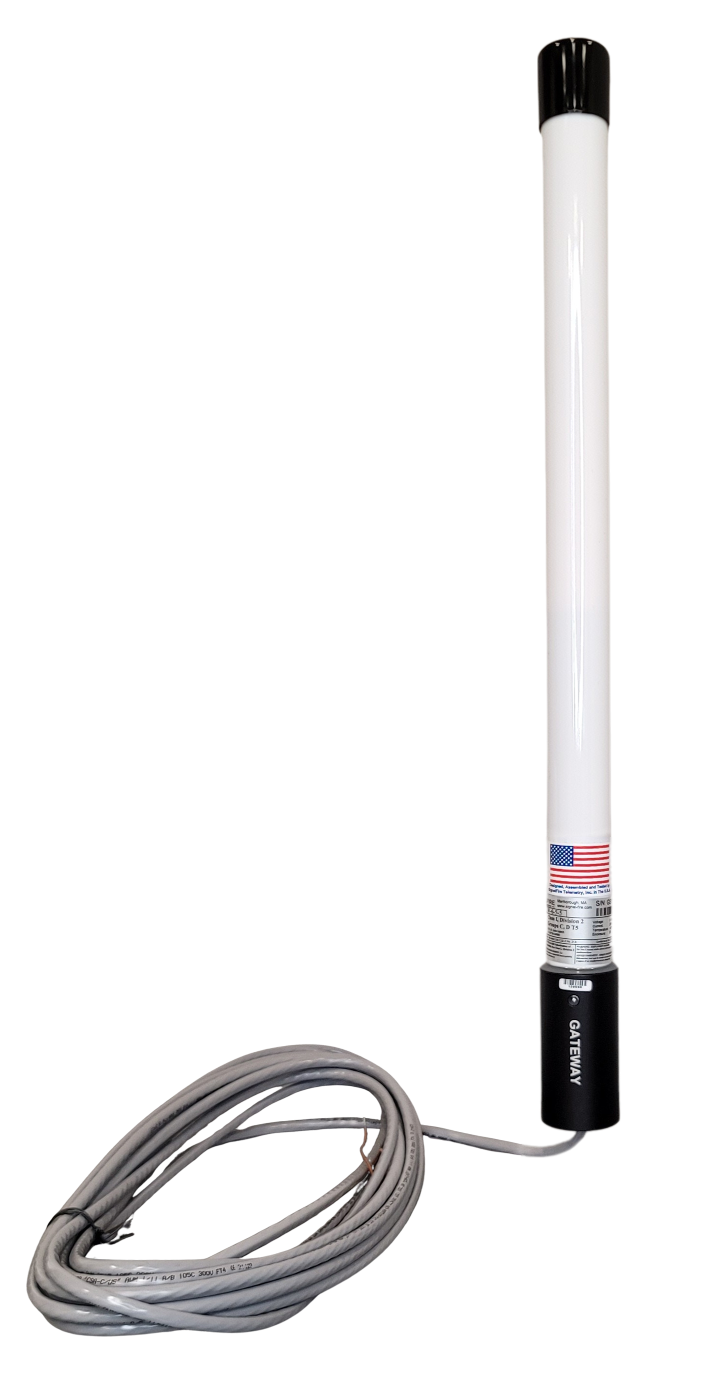
SignalFire Remote Sensing Systems (SFRSS) consist of radio nodes that integrate with different sensors to send process data to a Gateway, where it is transferred to a PC, PLC, or other control system to monitor assets such as silo temperatures, tank levels and other parameters. When using long-range Modbus stick nodes or wireless I/O modules (or Multiple I/O modules) as part of the SFRSS, these components are typically externally powered by a solar power system that consists of a 12V battery charged and a solar power panel.
Correct configuration of the solar powered battery system ensures autonomous battery operation without the presence of light for extended periods. SignalFire recommends following these specifications when sizing a solar power system for the SignalFire Modbus stick, wireless I/O module, RSD Stick or Gateway:
Based on using a 12 Volt system, battery “size” is expressed in amp-hours and is a measure of how much total power or capacity a battery can generate. The required battery capacity depends on the amount of (average) current to be drawn from the battery and the autonomy length. Following our basic rules, we want 10 days of autonomy to use ½ of the battery capacity.
Current draws vary by load. The current draw for standard configurations of SignalFire equipment is outlined in Table 1. Let’s say, we want to power a SignalFire Remote Shutdown Stick (Modbus Stick with Remote Shutdown Module) with a single relay that is almost always energized. According to Table 1, the current draw for the stick and module at 12 Volts is 34 mA.
Using this value, we can calculate the amount of capacity used in a day:
Based on 10 days of autonomy, capacity increases to:
As these calculations are based on only half the battery capacity, we need a battery with 2X this capacity or:
As batteries are available in capacities at rounded numbers such as 5, 10, 12, 15, 20, a 20 Amp-Hour battery would provide a little extra capacity or a 15 Amp-Hour battery would offer a little less capacity. If the SFRSS operates for long periods without sun, a 15 Amp-Hour battery is adequate but in areas with extended dark periods, a 20 Amp-Hour battery is recommended. Keep in mind that as the battery increases in capacity, so does its physical size.
Based on the battery size, we can determine the solar panel needed to charge this system. If using a 20 Amp-hour battery, we must half charge the battery at 10 Amp-Hours of capacity in 6 hours. The calculation for determining the needed charging current is:
Using this value, the size of the solar panel is calculated. Solar panels are measured in Watts, which is a measure of their power output. Watts equals current times voltage:
Based on these calculations, a 20 Watt solar panel is needed to charge a battery from half charge in about 6 hours. After determining the battery size (12 Volt, 20 Amp-Hour) and solar panel size (20 Watt) needed for this system, a charger is needed that can output at least 2 amps (5-10 Amps is common). SignalFire recommends the SunSaver solar charge controller from Morningstar to connect to the solar panel to charge the battery.
Table 1: Outlined is the current draw for standard configurations of SignalFire equipment. (Contact the factory for other configurations.)
Device |
Configuration |
Average Current (mA) |
| Modbus Stick | None | 18 |
| RSD System (Stick and Module) | 12V, both relays off | 18 |
| RSD System (Stick and Module) | 12V, one relay on | 34 |
| RSD System (Stick and Module) | 12V, both relays on | 50 |
| RSD System (Stick and Module) | 24V, both relays off | 12 |
| RSD System (Stick and Module) | 24V, one relay on | 22 |
| RSD System (Stick and Module) | 24V, both relays on | 30 |
| Gateway Stick | 12V | 25 |
| Gateway Stick | 24V | 17 |
| GW Stick with Enet Module | 12V | 85 |
| GW Stick with Enet Module | 24V | 57 |
| MIOM (module only) | 12V, No relays on | 2.0 |
| MIOM (module only) | 12V, 1 relay on | 9.6 |
| MIOM (module only) | 12V, 2 relays on | 16.7 |
| MIOM (module only) | 12V, 3 relays on | 24.3 |
| MIOM (module only) | 12V, 4 relays on | 31.1 |
| MIOM (module only) | 24V, No relays on | 1.3 |
| MIOM (module only) | 24V, 1 relay on | 5.8 |
| MIOM (module only) | 24V, 2 relays on | 9.6 |
| MIOM (module only) | 24V, 3 relays on | 13.6 |
| MIOM (module only) | 24V, 4 relays on | 17.0 |
| Modbus IO1 Module (module only) | 12VDC supply Relay off | 3 |
| Modbus IO1 Module (module only) | 12VDC supply Relay on | 10 |
| Wireless-IO Module | 15sec check-in. 12V, no relays | 21.1 |
| Wireless-IO Module | 15sec check-in. 12V, 1 relay | 36.5 |
| Wireless-IO Module | 15sec check-in. 12V, 2 relays | 51.5 |
For assistance in determining the solar-powered battery system for SignalFire equipment, contact technical support at: 978-212-2868 x2 or support@signal-fire.com. Read about how the Remote Sensing System with Solar-Powered Repeater Automates Liquid Storage Tank Level Monitoring here.
Get in Touch With Us and Tell Us About Your Toughest Monitoring and Control Challenges.