SignalFire Telemetry products connect you with crucial product and hardware data at any of your oil and gas operation sites—whether it’s a pump, pipeline, or storage tank.
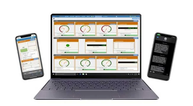
SignalFire Telemetry devices can monitor key assets and can do it affordably, without any renovation or high-priced engineering costs. They install easily with no required cable or additional power. The data is available on your phone or computer and the cloud service can even output to your corporate system to integrate with the rest of your data and keep your operation running.
SignalFire Telemetry devices can monitor and manage water supplies and additives throughout the property, helping you avoid catastrophic shortages and keep your irrigation plan on track.
Avoid costly product loss in bulk storage tanks, terminals, and transportation movements. Whether calling for tank levels, gauge pressure, or even movement pumps or pipelines, SignalFire products can fill any monitoring gap throughout a facility.
Environmental fines for businesses are frustrating and can bring business to a standstill until they’re worked out. No business wants to hurt the environment, and in competitive markets stopping production affects the bottom line and staff. But there are effective and affordable solutions with SignalFire Telemetry devices.
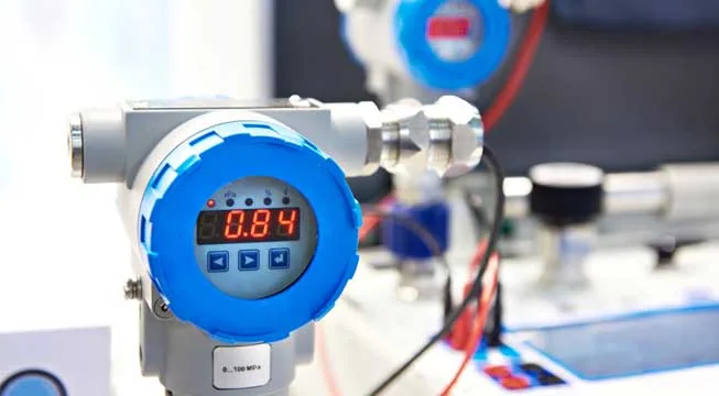
Expand visibility and control of your refinery or petrochemical processing facility without expensive renovations or redesigns. And do it with your current gauges and hardware. SignalFire telemetry devices are designed to work in harsh chemical environments and meet the strictest safety and security standards
No matter the size of your service map, monitoring remote assets ensures efficiency and keeps your operation in compliance. That’s how SignalFire devices can really help, offering the most affordable and effective monitoring solution that will monitor liquid, gas, electricity, and other assets.
Empowering Connectivity, Igniting Precision: Signalfire Telemetry, where data transforms into actionable intelligence, propelling industries forward with unmatched reliability and innovation.
2006
Established
5 Billion+
Hours of Operation
60+
Products
20+
Countries Served
160
Years of Combined R&D Expertise
2006
Established
5 Billion+
Hours of Operation
60+
Products
20+
Countries Served
160
Years of Combined R&D Expertise
Our Story
Why the name SignalFire?
Signal fires, which have been used for centuries, represent one of the earliest forms of long-distance communication, showcasing human ingenuity in overcoming the limitations of geography and distance. The long-range capability of our products, allows for data transmission over large distances, just as signal fires were visible from afar.
SignalFire DNA
We are committed to delivering exceptional customer service and maintaining responsiveness. Our team takes pride in promptly addressing customer inquiries and providing reliable support.
Our Product Philosophy/Value Proposition
When we design something, we design based on how our customers are going to experience the product. How the customer is going to make the product work.
Our commitment to our customers drives us to create versatile products that cater to a broad spectrum of applications. Whether you’re in the field or the control room, our solutions are engineered to seamlessly integrate into your operations, ensuring flexibility and performance.
Our Mission Statement
At SignalFire Telemetry, we are committed to revolutionizing industrial automation with our innovative wireless solutions. Our mission is to empower businesses by providing reliable, user-friendly, and versatile telemetry systems that enable seamless sensing, controlling, and monitoring without the constraints of wires. We strive to digitally transform operations, offering the flexibility and cost-effectiveness of our products to meet the unique challenges of each industry. As a leader in wireless automation, we are dedicated to connecting the world’s critical assets and data, fostering efficiency, safety, and sustainability for a smarter future.
We are part of a big family
TASi Measurement is a thriving global industrial measurement and monitoring business headquartered in North America. We provide temperature, level, flow, and pressure instruments necessary to measure and control industrial processes and monitor our environment. We also facilitate data gathering and reporting from our instruments and others with our remote telemetry products that include RF and Cellular options as well as Remote SCADA solutions purpose built for specific applications. We operate in a decentralized manner and have fifteen business units with production facilities in the United States, Canada, Switzerland, Germany, and England. Additional sales offices can be found in China, Netherlands, and Malaysia.
TASI Measurement’s portfolio includes brands like Air Monitor, AW-Lake Company, EXACT Dispensing Systems, Fox Thermal, Greyline, KEM-Küppers, Litre Meter, Mission Control, ONICON, Pulsar, Pyromation, Seametrics, Sierra Instruments, TRICOR Coriolis, Vortek, and Vögtlin Massflow.
Being a part of TASI Measurement, SignalFire contributes to serving companies worldwide across diverse industries, including oil & gas, water and waste water, municipal, environmental, agriculture, marine, industrial manufacturing, refining, chemical processing and more. We are committed to providing innovative wireless telemetry solutions to enhance efficiency, reliability, and safety in our clients’ operations.
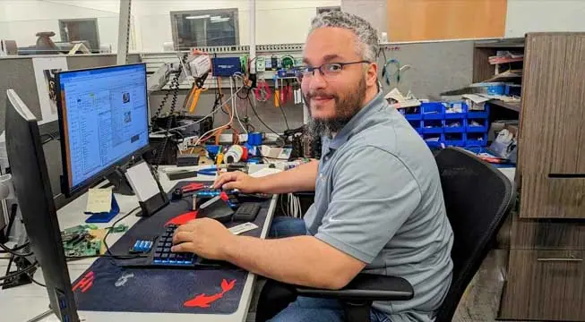
As the General Manager and CTO of SignalFire Wireless Telemetry, Josh Schadel leads the company’s innovation and growth in the field of wireless automation solutions for industrial applications. He has over 25 years of expertise in high tech instrumentation, specializing in embedded systems and low-power wireless sensor networks. He was a key contributor to SignalFire’s product development and technology since he joined the company in 2008 as the Director of Engineering. Josh graduated from Worcester Polytechnic Institute with a bachelor’s degree in electrical and computer engineering. When he is not working, he likes to spend time outdoors with his family and pursue his passion for cars and racing.
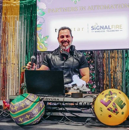
Sandro Esposito serves as Vice President of Sales & Marketing for SignalFire Telemetry Inc, with responsibilities for managing the portfolio and commercialization of the company’s wireless telemetry solutions. In addition to possessing more than 30 years of experience in the process control and automation industry, he holds six patents and has published 15 papers related to industrial controls and smart technologies. A graduate of College Ahuntsic in Montreal, he holds a Bachelors degree in electrical and instrumentation engineering and is actively involved in the International Society of Automation. In his free time, he is recognized as DJ Sandman, showcasing his expertise as a disc jockey.
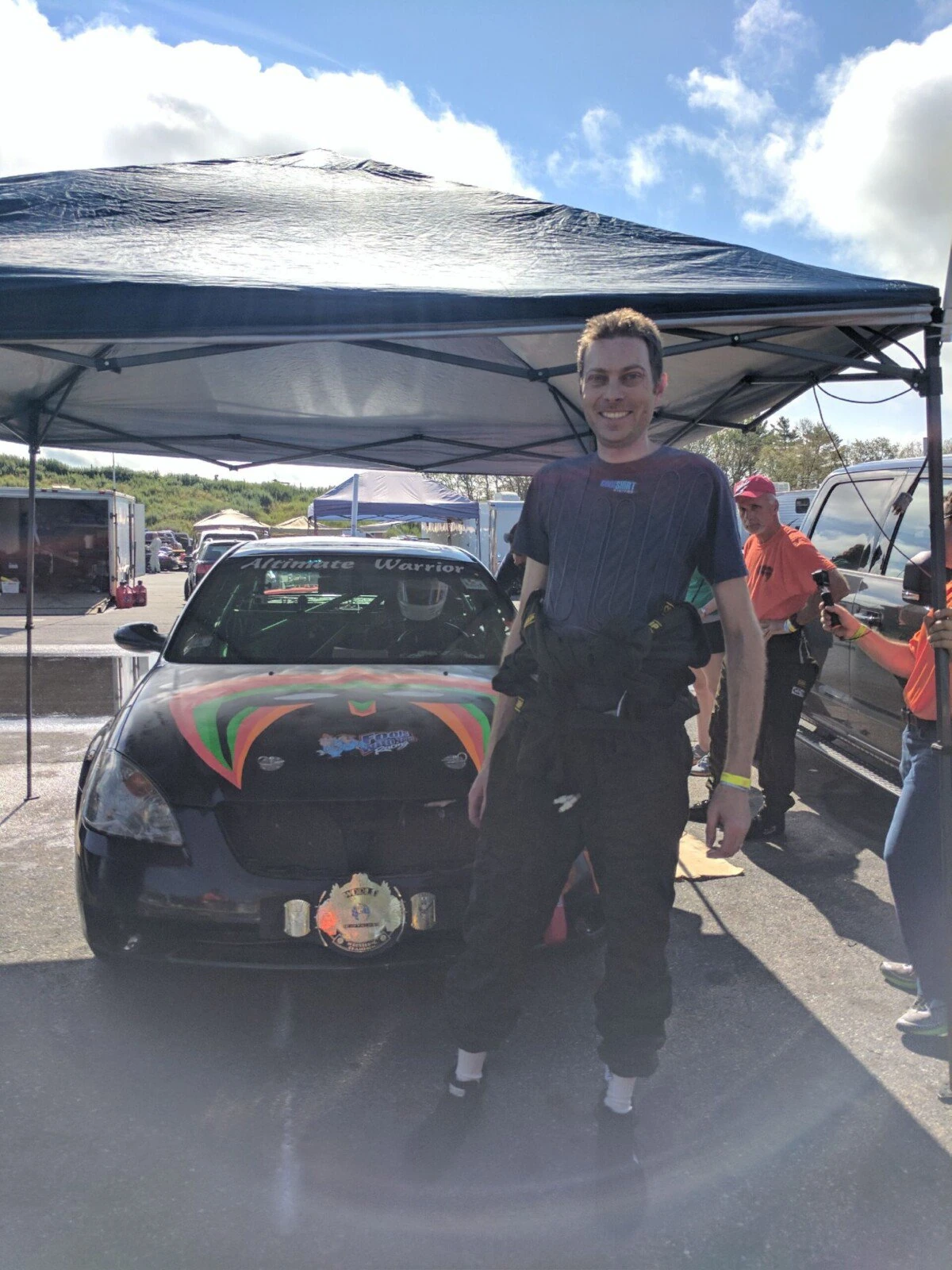
Aaron Jones serves as Production Manager for Signalfire Telemetry. He brings 20 years of experience overseeing supply chain and manufacturing operations; specializing in wireless and IOT devices. His determination to maintain high quality products and industry leading on time delivery serves a critical role in SignalFire’s ongoing commitment to customer satisfaction. When not at the office, Aaron also directs a multi car, class winning endurance racing team participating in the 24 Hours of Lemons series.
Lee Ann Meier is the Marketing Communications Specialist at SignalFire Telemetry, leveraging two decades of expertise in design and marketing. With a strong educational background including degrees in Art, Graphic Design, and Web Design, Lee Ann possesses a deep-seated passion for creative expression and collaboration. Her commitment to fostering teamwork and pushing the boundaries of innovative design solutions fuels her professional drive. At SignalFire Telemetry, Lee Ann is dedicated to crafting compelling narratives and visually captivating content that resonates with audiences. In her free time, she enjoys spending time with her family, watching her kids play sports, playing volleyball, golfing, and bowling.
Devin Gates serves as a Sales and Marketing Specialist at SignalFire Telemetry, bringing more than a decade of experience in the measurement and control industry. He has worked with multiple manufacturers as well as in the manufacturer representative channel, supporting leading brands including Schneider Electric (Foxboro), FLEXIM, AMETEK, and VEGA.
Devin has a genuine passion for measurement technology and an insatiable drive to keep learning. Outside of work, he enjoys spending time with his wife, Elizabeth, and their two cats, Alice and Cooper. His hobbies include playing guitar, writing, and listening to heavy metal music.
Troy McLean serves at the Director of Business Development for Water & Utilities with SignalFire Wireless Telemetry with responsibilities of helping the sales team break into new markets and to provide insight of customer requirements for new products and services. He has 38 years of technical sales leadership in flow, pressure, temperature, and level instrumentation along with data acquisition and telemetry solutions across multiple industries. Troy is certificated FAA remote pilot. He enjoys wildlife photography and videography and is always in search of that perfect Moose photo.
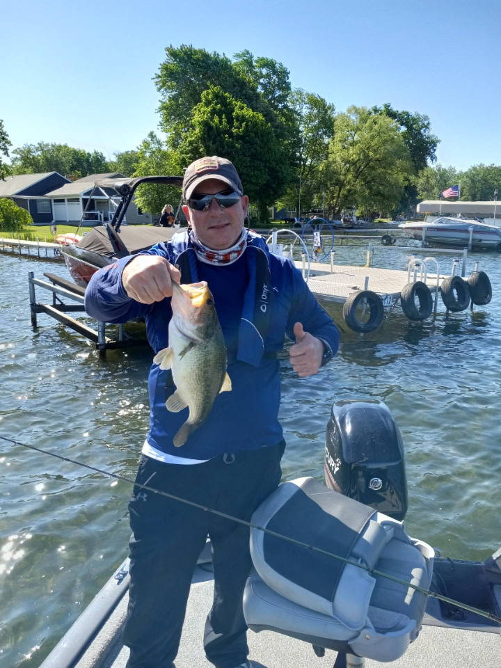
Tim Surphlis is a 30-year industry veteran with experience that spans from valves, pumps and piping to instrumentation in the Nuclear Power, Fossil Power and Oil & Gas Industries. As a Regional Sales Manager for Signal Fire Wireless Telemetry, Tim covers the Southeastern United States as well as Latin America. Tim has a BA Degree in Business from Stetson University and a BS Degree in Electrical Engineering Technology from DeVry Institute of Technology and is fluent in English in Spanish. Tim likes to spend time with his family and enjoy lake activities from fishing to skiing and wakeboarding.
Russell Hall serves as the National Sales Manager for Oil and Gas at SignalFire Wireless Telemetry, where he oversees sales strategy and provides critical support for manufacturer representatives. With over 40 years of experience in automation, including 20 years specializing in the commissioning and deployment of wireless technologies, Russell bridges the gap between complex technical requirements and practical, customer-centric solutions.
His career is built on a foundational expertise in the field, having served seven years as an instrument technician. This hands-on background, combined with an Associate degree in Instrumentation, allows him to provide uniquely informed technical guidance for digital transformation in the oil and gas sector.
Russell has authored and presented numerous technical papers at industry trade shows on topics including viscosity, custody transfer, specific gravity, density, and wireless instrumentation. His expertise has also led him to serve as a technical advisor to several American Petroleum Institute (API) committees. Outside of his professional endeavors, Russell enjoys culinary arts and spending time at a lakeside retreat.
Scott Ceci serves as the Northeast Regional Sales Manager. He brings over 20 years of diverse experience spanning data centers, hospitals, utilities, and more. With a strategic blend of SaaS, AI, and Enterprise software, he tackles complex challenges in utility, telecom, commercial, and industrial sectors. With an unwavering commitment to excellence and innovation, Scott delivers value and success in every endeavor. Scott offers expertise, strategic vision, and proven leadership to help you achieve your goals. In his free time, he enjoys fishing and spending time with his family.
Dean serves as the Western Regional Sales Manager for USA and Canada. He is celebrating 40 years in the Industrial Process Automation industry with a renewed joy in working for such a great company and products. Dean has been blessed with a wonderful wife- (celebrating 35 years), father of two and grandfather of twins. Dean also enjoys everything outdoors and especially biking and hiking.
Sven Fielder serves as a Regional Sales Manager for SignalFire Wireless Telemetry, covering the Permian Basin and Oklahoma Basin. Born in Germany to a U.S. Army family and raised in Texas, Sven brings decades of public service and technical sales experience to his role. He spent 25 years serving as a Firefighter, Paramedic, and Law Enforcement Officer, working across specialized units including arson investigation, hazardous materials, K9, narcotics, gang enforcement, and rescue operations. Throughout his career, he earned numerous honors, including the Meritorious Service Award and Life Saving Award.
After retiring from public safety, Sven transitioned into sales, concentrating on sensors, automation, and control solutions with a strong focus on water and wastewater applications. Sven has been married to his wife, Aleese, for 30 years, and they have two grown children, including a son serving full-time with the Wisconsin National Guard. In his free time, he enjoys traveling, shooting sports, fishing, and collecting autographed first editions of major novels.
Jack Keller serves as Regional Sales Manager for the Midwest Region at SignalFire Telemetry. He brings a strong background in the manufacturers’ representative business, having built his career selling process instrumentation across industries including steel, chemical, petrochemical, and food & beverage. His experience spans temperature, pressure, flow, level, and gas detection solutions, and he has earned multiple sales achievement awards for his performance and customer focus.
Originally from the Cleveland, Ohio area, Jack is a proud graduate of The Ohio State University. He is excited to help expand SignalFire’s presence while supporting customers and partners throughout the Midwest. Jack is married to his wife, Shirley, and together they have two wonderful children. As a family, they enjoy spending time outdoors and staying active whenever they can.
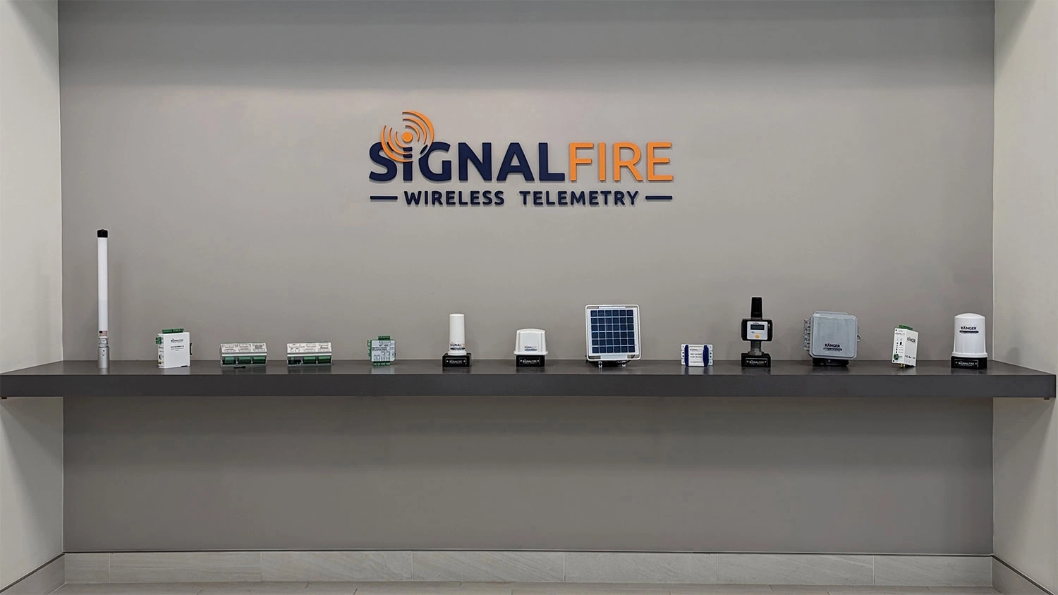
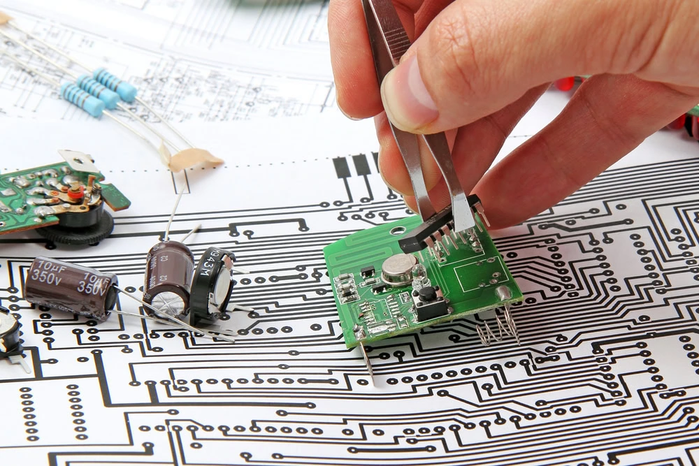
SignalFire Wireless Telemetry specializes in the design and manufacture of low-powered industrial solutions, revolutionizing the way sensing, controlling, and monitoring are conducted without the constraints of wires. Our cutting-edge platform is compatible with a wide range of industrial sensors and offers versatile connectivity options, including 900MHz Radio Frequency or Cellular & Cloud with LTE-M1, ensuring flexibility and cost-effectiveness.
Designs for Harsh Environments
Our products are designed to be durable and certified for tough environments, incorporating a secure communication protocol. This allows for long-distance wireless communication, efficiently connecting multiple devices in challenging outdoor settings. At SignalFire, our main goal is to help users digitally transform their operations by effortlessly integrating existing or new sensors without the need for wires, cables, or conduits.
Testimonials
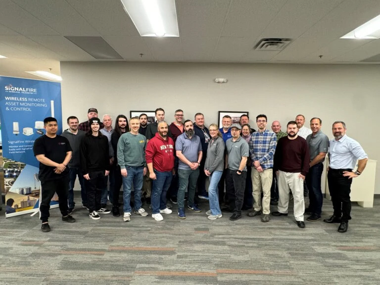
The Impact We’ve Made for Our Team
I work with an amazing team of wireless telemetry experts that are always happy to lend a hand or share advice. Everything begins with a positive attitude and a love for the product and technology. We all take pride in what we do every day and it shows in our quality, workmanship and on time deliveries.
Tim Surphlis
It’s a great feeling to work for a company where everyone is appreciated and cared for.
Sandro Esposito
SignalFire is great at finding roles for people that fit their interests and skills.
Sam Blodgett
I love working at SignalFire because of our culture! It’s instilled in all of us to be creative in helping our customers to be successful through thought provoking application support and new products and services that our customers ask for. We’re able to deliver new and existing solutions to the market faster than any company that I have ever worked for.
Troy McLean
Join Our Amazing Team
Join our incredible team and embark on a journey filled with innovation, collaboration, and endless opportunities to shine! Let’s create magic together
Thank You for Your Interest in Signalfire Wireless Telemetry Products
Contact us today to request a quote, obtain authorization for sending a product covered by our warranty, or if you need help with technical issues or troubleshooting, our tech support is here to assist you!


